


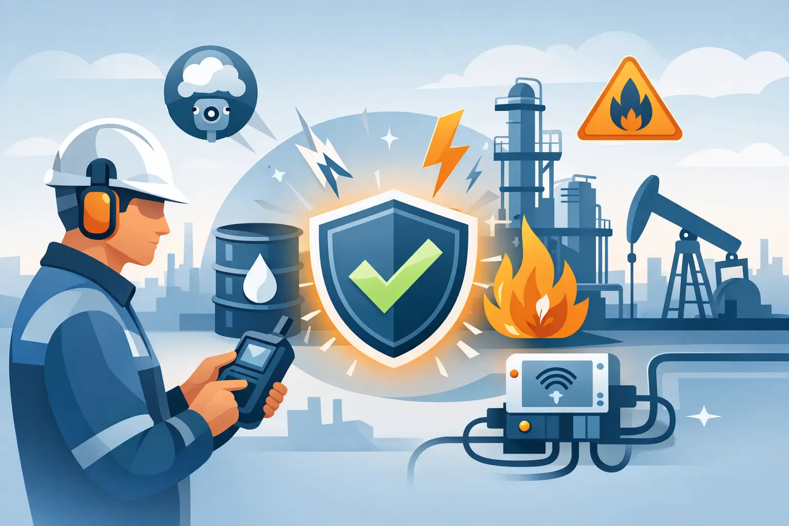
Intrinsic Safety Design Guide for Hazardous Areas
A control loop can look perfectly correct on a panel drawing and still fail a hazardous-area review for one reason: the energy available in the field circuit was never evaluated as part of the design. That is where an intrinsic safety design guide becomes useful – not as a paperwork exercise, but as a method for limiting ignition risk at the circuit level before installation, commissioning, or inspection.
Intrinsic safety is often treated as a product feature. In practice, it is a system design discipline. The transmitter, isolator, cable, simple apparatus, grounding method, control cabinet layout, and hazardous-area classification all affect whether the final loop is compliant. For plant engineers and OEMs working in oil and gas, chemical processing, marine, hydrogen, mining, and other high-risk environments, that distinction matters because small design errors can lead to noncompliance, nuisance shutdowns, rework, or a rejected project file.
What this intrinsic safety design guide is really about
At its core, intrinsic safety limits electrical and thermal energy in a circuit so that ignition cannot occur under defined normal and fault conditions. That principle sounds straightforward. The challenge is that compliance is not established by a single device label alone. It is established by the relationship between connected equipment and the installation conditions.
An intrinsically safe loop typically includes field equipment in the hazardous area, associated apparatus or an intrinsically safe isolator in the safe area, interconnecting cable, and any accessories such as indicators, HART interfaces, or multiplexing systems. Each part must be considered against the relevant certification basis, whether ATEX, IECEx, FM, or another scheme used by the project.
This is why experienced teams review intrinsic safety as early as instrument index development and I/O architecture definition. If that review is delayed until procurement or site acceptance testing, the available device choices may no longer support the required gas group, temperature class, entity parameters, or segregation rules.
Start with area classification, not the product catalog
A sound intrinsic safety design guide starts with the hazardous-area data. Before selecting barriers or isolators, define the zone or division, gas or dust group, ambient conditions, temperature class, and installation constraints. A loop intended for Zone 1 gas service may need a different approach than one installed in a dust environment or in a location with elevated ambient temperature inside an enclosure.
This is also the stage where design teams should separate what is known from what is assumed. If the gas group is uncertain, if ambient temperature peaks are not documented, or if field cable routing is still fluid, those uncertainties should be visible in the design basis. Intrinsic safety calculations are only as reliable as the inputs behind them.
Another practical point is maintenance philosophy. Some plants strongly prefer live maintenance capability, while others prioritize standardization across all loops. Intrinsic safety is often attractive because it supports work in hazardous areas without the same shutdown implications associated with some other protection methods. But that benefit only holds when the installation and documentation are disciplined.
Choose the protection architecture carefully
In most instrument loops, the first major decision is whether to use zener barriers or galvanically isolated barriers. Both can be suitable, but the trade-offs are real.
Zener barriers are familiar and cost-effective in many applications, but they depend on a high-integrity grounding system. If grounding quality is questionable, if there is high electrical noise, or if multiple references create circulating current concerns, the installation can become harder to manage. Galvanic isolators generally offer easier integration, reduced grounding dependency, and better signal integrity in modern automation systems, especially where HART transparency, analog accuracy, and cabinet flexibility matter.
For packaged systems, remote I/O, and brownfield upgrades, isolator selection also affects panel density, heat dissipation, maintenance access, and diagnostics. A lower component price on paper does not always produce a lower installed cost once cabinet design, commissioning time, and future troubleshooting are considered.
Entity parameters decide whether the loop is valid
The most common design mistake is assuming that matching voltage and current ratings is enough. It is not. Intrinsic safety requires checking the output parameters of associated apparatus against the input parameters of the field device, along with cable capacitance and inductance.
In practical terms, the maximum open-circuit voltage and short-circuit current of the barrier or isolator must be compatible with the field device. The permissible external capacitance and inductance must also cover the actual cable and device contribution. If the cable run is long, if multicore cables are used, or if several simple apparatus elements are included, those values can become the limiting factor.
This is one reason loop-by-loop verification is still necessary, even when the same transmitter model is repeated across the plant. Cable lengths, routing, gland arrangements, and accessories often differ. A design that passes in one unit may fail in another with seemingly minor changes.
Cable, grounding, and segregation are not secondary details
A compliant certificate set can still lead to site issues if installation practice is weak. Cable selection should support the electrical calculation and the mechanical environment. Shielding, conductor resistance, insulation type, and routing all matter in high-noise or corrosive areas.
Segregation is equally important. Intrinsically safe circuits must be separated from non-intrinsically safe wiring according to the applicable standard and the equipment manufacturer instructions. This affects marshalling cabinets, junction boxes, trunking, terminal identification, and maintenance work practices. Where blue identification is used for intrinsically safe circuits, it should be applied consistently to reduce field confusion.
Grounding deserves special attention. With zener barrier systems, grounding integrity is fundamental to safety. With galvanic isolation, grounding design still affects EMC performance, signal stability, and surge behavior. Plants with frequent lightning exposure or heavy motor loads should coordinate intrinsic safety with surge protection and overall earthing philosophy rather than treating them as separate disciplines.
Certification must match the real installation
A certificate is only meaningful when it matches the application. That sounds obvious, but project teams still run into trouble with mixed approvals, incomplete documentation, or field substitutions that invalidate the original design intent.
The device marking should be checked against the hazardous location, gas or dust group, EPL or zone requirement, and temperature class. Ambient range is often overlooked, especially for panel-mounted interfaces in hot climates or compact enclosures. Functional safety requirements add another layer. If the loop is part of a SIL function, the intrinsic safety solution and the functional safety architecture both need to be satisfied.
This is where disciplined suppliers add value. A component may be certified, but if the technical file does not support entity matching, loop drawings, declaration review, and installation guidance, the burden shifts back to the EPC, OEM, or plant engineer.
Intrinsic safety design guide for common loop types
Analog input loops are usually straightforward, but HART communication can expose weak device selection. Not every barrier or isolator preserves HART effectively, especially across longer cable runs or mixed system interfaces. If asset management and remote diagnostics are part of the operating philosophy, HART compatibility should be confirmed early.
For vibration monitoring, pulse, switch, and frequency signals, signal integrity becomes more sensitive. Proximity probes, NAMUR sensors, and vibration transmitters may have specific interface requirements that narrow the list of approved isolators. The same applies to shutdown systems, where line fault detection, response time, and proof test strategy can influence the architecture.
Solenoid and output loops require even closer review. Delivering adequate field energy to actuate a device while remaining within intrinsic safety limits is not always simple. In some cases, intrinsic safety is the right method. In others, another protection concept may be more practical. Good engineering means recognizing where intrinsic safety is the best fit and where it creates unnecessary complexity.
Documentation is part of the safety case
An intrinsic safety design guide is incomplete without documentation control. The loop drawing, hazardous-area schedule, cable schedule, certificates, datasheets, and calculation sheets should all tell the same story. If site personnel cannot trace a field device to the approved barrier, cable, and loop parameters, maintenance risk increases.
Document discipline also reduces lifecycle problems. Plants change. Instruments are replaced, panels are expanded, and shutdown systems are modified. If the original intrinsic safety basis is clear, future changes can be reviewed without reopening the entire design philosophy.
For that reason, many operators standardize approved interface families for analog, digital, HART, and safety-related loops. Standardization does not replace engineering judgment, but it improves repeatability and reduces errors during procurement and maintenance.
Where projects usually go wrong
Most intrinsic safety issues are not caused by exotic technical failures. They come from ordinary project shortcuts: selecting components before confirming area classification, copying loop designs without recalculating cable parameters, ignoring ambient temperature inside enclosures, mixing certification schemes without review, or treating hazardous-area compliance and SIL compliance as separate packages.
The better approach is to review hazardous-area protection, signal performance, maintenance needs, and certification together. That is how reliable loop design is built in demanding environments. Companies such as Arya Automation tend to be brought in at this stage because the issue is no longer product availability alone – it is whether the final system will pass review, operate reliably, and remain supportable over time.
A well-executed intrinsic safety design is rarely visible once the plant is running. That is exactly the point. The right loop architecture, certified interfaces, and disciplined documentation keep attention where it belongs – on stable production, safe maintenance, and equipment that performs as specified when the environment is least forgiving.