


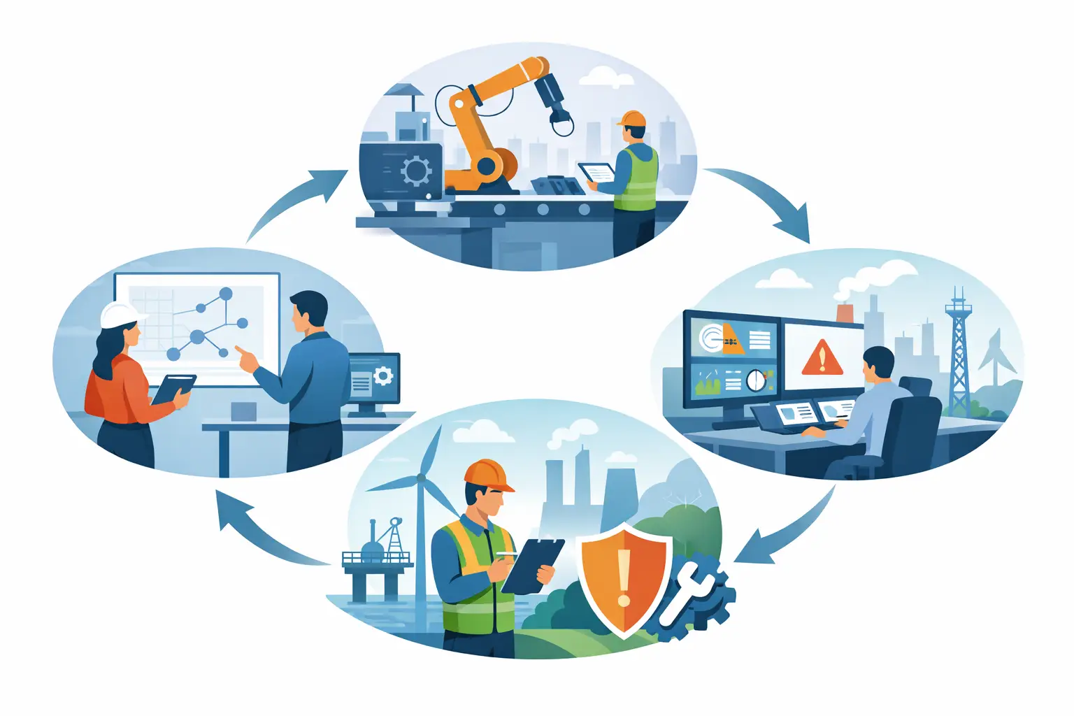
Functional Safety Lifecycle Explained
A safety instrumented function rarely fails on paper. Trouble starts when a good-looking design meets real operating conditions – process upsets, bypasses, undocumented changes, poor proof testing, and aging field devices. That is exactly why the functional safety lifecycle matters. It provides a disciplined framework for taking a safety function from concept through operation and modification, with traceability at every stage.
For plants handling hydrocarbons, chemicals, hydrogen, combustible dust, or critical utilities, that discipline is not optional. It is how teams turn safety targets into implemented, validated, and maintainable protection layers. The lifecycle is also where certification, device selection, and engineering practice meet. SIL-rated components are part of the picture, but they do not create a safe system by themselves.
What the functional safety lifecycle actually covers
The functional safety lifecycle is defined in standards such as IEC 61508 and applied in process industries through IEC 61511. In practical terms, it is the full sequence of activities required to specify, design, verify, install, operate, maintain, and eventually modify or decommission safety-related systems.
That scope is wider than many projects assume. Teams often focus heavily on front-end design and factory acceptance testing, then give less attention to proof testing, management of change, diagnostic coverage in operation, or failure data review. The result is predictable: the installed system may meet its target on day one, then drift away from its intended risk reduction over time.
A proper lifecycle approach prevents that drift. It forces clear definition of hazards, required risk reduction, architecture, device behavior, test intervals, documentation, and responsibilities before the system is trusted in service.
Why the lifecycle matters more than a SIL label
It is common to see procurement or project teams ask for SIL2 or SIL3 components as if the component rating alone determines system integrity. It does not. A certified relay, isolator, logic solver interface, vibration monitor, surge protection arrangement, or field barrier only contributes correctly when it is selected for the application, integrated within the right architecture, and maintained according to the safety requirement specification.
For example, a safety loop in a hazardous area may include signal isolation, intrinsic safety interfaces, field sensors, final elements, and control logic from multiple vendors. Even when every item carries the right certification, the loop can still fail its intended function if response times are not matched, proof test assumptions are unrealistic, common cause failures are ignored, or the bypass philosophy is weak.
The lifecycle addresses those gaps. It treats functional safety as an engineering process, not a product checkbox.
Functional safety lifecycle stages in practice
Hazard and risk assessment
The lifecycle starts with understanding what can go wrong and what the consequences are. In process plants, that usually means structured studies such as HAZOP, layer of protection analysis, or other risk assessment methods. The goal is to identify hazardous scenarios, existing safeguards, and the additional risk reduction required.
This is where many later design decisions are set. If the hazard study is shallow, the resulting safety functions are often vague or incomplete. If it is rigorous, the project team can define credible demands, process trip points, safe states, environmental constraints, and operator actions with much more confidence.
Safety requirements specification
Once hazards are understood, the next critical document is the safety requirements specification, often called the SRS. This is the technical contract for each safety instrumented function. It should define what initiates the trip, what action must occur, how fast it must happen, what diagnostics are expected, what proof test interval is assumed, and what happens under fault conditions.
A strong SRS also covers interfaces that are frequently overlooked, including HART transparency requirements, line fault detection, voting logic, reset behavior, and restrictions in hazardous areas. For plants using intrinsically safe isolators, SIL relays, or Ex-certified interfaces, these details affect both compliance and actual field performance.
Design and engineering
This stage turns requirements into architecture. Sensors, logic solvers, relays, isolators, final elements, and supporting power and interface hardware are selected and integrated. The design must consider SIL calculations, systematic capability, environmental limits, wiring practices, failure modes, and maintainability.
Trade-offs matter here. A highly available design may reduce nuisance trips, but complexity can introduce diagnostic blind spots or increase common cause exposure. A simpler loop may be easier to maintain, but it might not meet the required risk reduction without tighter proof test intervals. The right answer depends on the process, demand rate, maintenance capability, and shutdown philosophy.
In hazardous-area applications, engineering decisions are even tighter. Intrinsic safety parameters, segregation, grounding, surge protection, and approved installation methods have to align with both the safety function and the area classification. This is where an engineering-led supplier adds value beyond product availability.
Verification and validation
Verification asks whether the design matches the specification. Validation asks whether the installed system performs the intended safety function in the actual application. Both are necessary, and they are not the same exercise.
Verification includes calculation reviews, architecture checks, cause-and-effect confirmation, and document traceability. Validation takes place closer to commissioning and startup, where field devices, panels, logic, alarms, trip actions, and fail-safe responses are tested as a complete system.
The common mistake is to rely on bench tests and accept that as sufficient evidence. Real validation must reflect installed wiring, operating logic, field conditions, and interfaces to the basic process control system where relevant.
Operation is part of the functional safety lifecycle
A safety function that is never proof tested is only assumed to work. Once a plant enters operation, the functional safety lifecycle continues through maintenance, testing, competence management, incident review, and periodic assessment.
Proof testing is a major control point. If the test interval used in SIL verification is not achievable in the field, the claimed integrity may be overstated from the start. If testing is performed but not documented correctly, the plant loses traceability and cannot confirm that dangerous undetected failures are being managed.
Maintenance strategy also matters. Devices in corrosive areas, offshore environments, high-vibration zones, or extreme temperature conditions may degrade differently from assumptions made during design. Vibration monitoring, field diagnostics, line monitoring, and periodic inspection all help close that gap between theoretical performance and actual service behavior.
Competence is another operating issue that standards treat seriously. Safe systems depend on trained people making correct decisions under normal and abnormal conditions. That includes operators managing bypasses, technicians performing proof tests, engineers reviewing modifications, and procurement teams selecting equivalent replacements.
Modification is where many systems lose integrity
Very few industrial plants stay unchanged. Process conditions evolve, throughput increases, equipment is replaced, and control philosophies are revised. Each change can affect the original basis of safety.
A transmitter replacement may introduce different failure behavior. A logic change may alter trip response time. A panel retrofit may affect segregation or surge resilience. Even a seemingly small substitution, such as a different isolator or relay, can invalidate assumptions in the original safety assessment if certifications, diagnostics, or failure rates differ.
That is why management of change is a core lifecycle requirement. Every modification should be reviewed against the SRS, verification records, and operating procedures. If the change affects the safety instrumented function, the documentation and validation need to be updated accordingly.
What good lifecycle execution looks like
In well-run projects, the functional safety lifecycle is visible in the documents and in the hardware. Hazard studies connect clearly to the SRS. The SRS connects to loop design, device certification, and test procedures. Proof testing aligns with the assumptions used in SIL verification. Modification records are current. Responsibilities are assigned, not implied.
Just as important, good lifecycle execution is realistic. It does not assume perfect maintenance access, unlimited shutdown windows, or ideal environmental conditions. It accounts for actual plant constraints and selects technologies that support them, whether that means SIL2/SIL3 interfaces, intrinsically safe signal conditioning, certified surge protection, or field-proven monitoring devices suited for harsh industrial service.
For companies operating in hazardous and high-consequence environments, that level of discipline protects more than compliance. It protects uptime, asset integrity, and confidence in the layers that must work when normal control no longer can.
Arya Automation works in exactly that space, where certified components, application knowledge, and disciplined engineering have to align. The value is not simply supplying approved hardware. It is helping ensure that hardware supports a safety function throughout its full service life.
The useful question for any plant is not whether a system was designed to be safe. It is whether the safety intent can still be demonstrated today, in the field, under actual operating conditions.